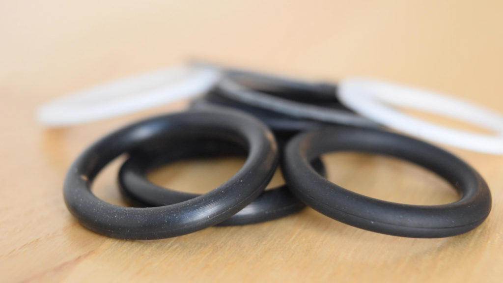
O-rings are the epitome of elegant engineering: The ring itself costs only a few cents, and the groove it goes in is simple and easy to manufacture. But despite this simplicity, the resulting seal is able to reliably hold many thousands of psi of pressure. O-rings are definitely a machine design component you’ll want to be familiar with, and in this video, we’re going to tell you all about how to design seals with them.
An O-ring forms a seal when it is squeezed between two adjacent surfaces. As the ring is squeezed, a contact stress between the O-ring and the surfaces emerges. If the fluid pressure is lower than the contact stress, then the seal prevents the fluid from escaping. In general, as the fluid pressure increases, the O-ring is compressed even tighter into the groove, further increasing the contact pressure, and hence helping the O-ring to seal even better. This positive feedback loop of increasing pressure leading to increased sealing is called “self-energizing”.
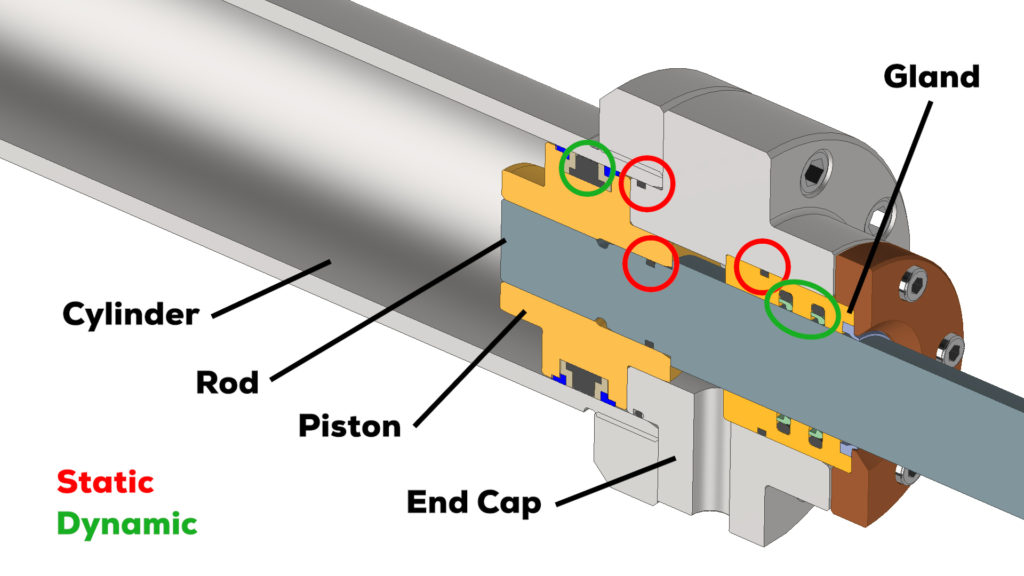
Seals can be generally classified as either static or dynamic. This hydraulic cylinder has examples of both. The seals between the cylinder and the end cap, the gland and the end cap, and the piston and the rod are static seals, since these components don’t move relative to one another after the cylinder is assembled. The seal between the piston and the cylinder, and the rod and the end cap are dynamic seals, since these components slide when the cylinder is actuated.
The most common type of seal is a radial seal, which can be designed in one of two ways. If the groove is on the ID of the housing, this is called a rod seal. If the groove is on the OD of the shaft, then this is a piston seal. If you have a choice between a rod and piston seal, it’s better to go with a piston seal, because the grooves are much easier to machine and inspect.
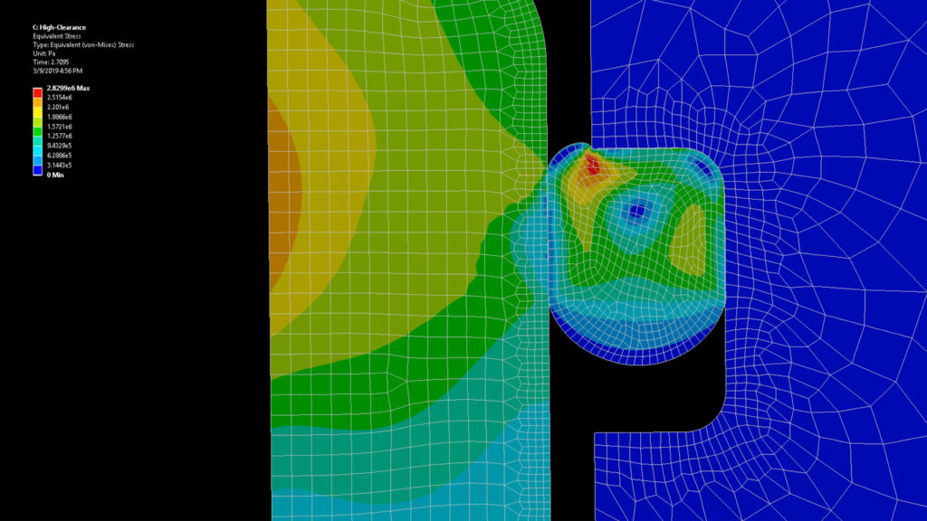
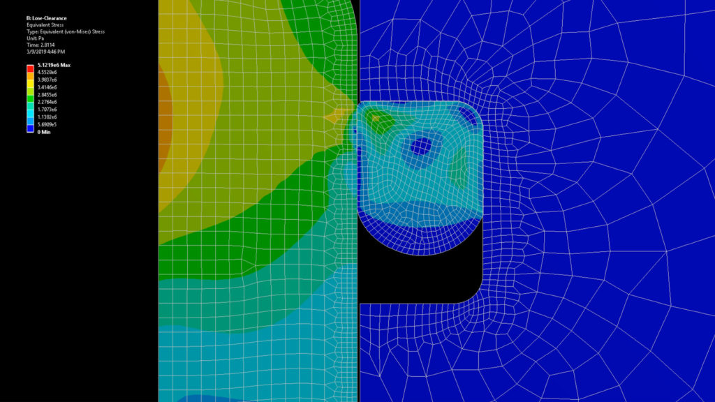
The biggest weakness of radial O-ring seals is that the clearance between components creates a path for the O-ring to extrude due to the pressure acting on it. Components called backup rings can help alleviate this. Backup rings are designed to spring out of the gland and block the extrusion gap. Where an O-ring alone could withstand perhaps only 2000 psi, a backup ring can help it hold 5000 or more.
Backup rings are very cheap, and effective. They are made of a plastic like PEEK or Teflon, and they usually have a scarf cut to help you install them in the gland. Technically speaking, if you only had pressure in one direction, you could get by using only one backup ring. However, it’s very easy to put the ring in on the wrong side, so as a design-for-assembly precaution, if designing with backup rings, you should always design for two.
Another configuration is a face seal, which you might use when trying to seal an enclosure. These are really a type of gasket, and they require a clamping force, usually provided by fasteners, to compress the O-ring. Face seals are actually really tricky to get right, because squeezing the O-ring requires a great deal of pressure. This first lid design is far too thin, and in the middle, there is virtually no squeeze on the O-ring, and hence no sealing. We can fix this design by adding a lip around the perimeter.
A third type of design is a boss seal. You pretty much only see them on hydraulic fittings, but they have a lot of advantages for other applications. In this configuration, the O-ring sits in a triangular space that is usually made with a special form tool. Boss seals are really easy to manufacture, since there aren’t any undercuts, and if the gland gets damaged, they can be reworked by just machining the profile slightly deeper.
Regardless of the gland design you select, you’ll likely need to choose an off-the-shelf O-ring from a catalog. O-rings are available in standardized sizes. The most common standard is AS568, and each size is assigned a “dash” number.
O-rings conforming to these sizes are available in many different materials. The primary considerations for selecting a material is the working fluid and temperature. Design tables, like this one in the Parker O-ring Handbook, are the easiest way to select a material that is appropriate for your application.
The same material is often available in a range of different hardnesses. The hardness is typically expressed as the Durometer Hardness. 70 is a fairly typical hardness and is good for most uses. 55 Durometer is much softer, and is a good choice for pressures below maybe 1000 psi because it is easier to install and less sensitive to surface finish.
90 Durometer is extremely hard, and consequently, is more resistant to extrusion. For higher pressures, exceeding maybe 6000 psi, you’ll definitely want to consider using 90 durometer.
However, the better high-pressure performance comes at a price. 90 durometer O-rings can be really difficult to install, particularly in small sizes. A good tip is to drop them in hot water for a few minutes to let them soften. They will be a bit easier to install.
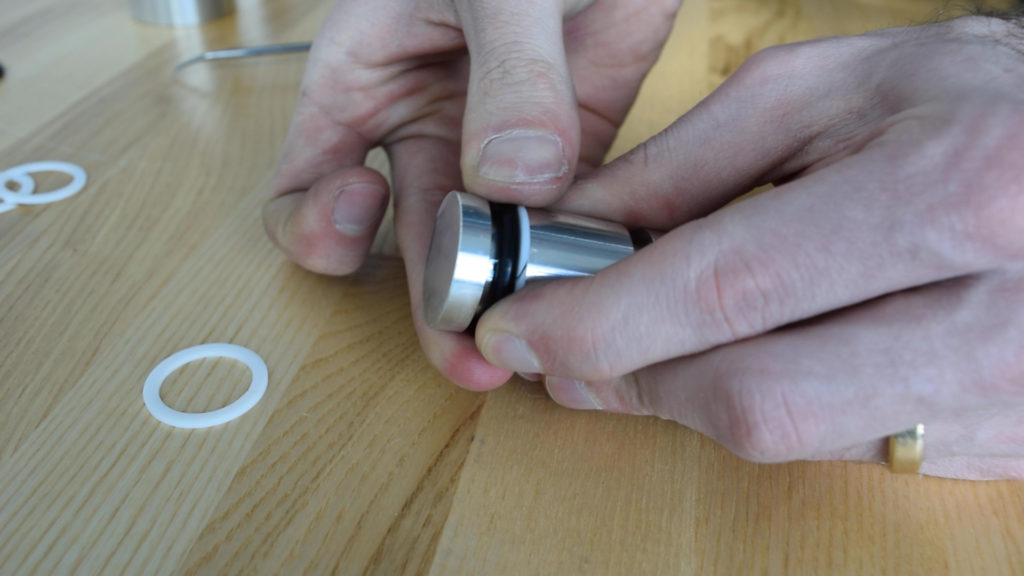
Another important installation tip is to apply a high-quality O-ring grease before assembling the parts. In addition to lubricating the rubber and helping it slide in easier, most O-ring grease is designed to cause the O-ring to swell slightly, helping increase the squeeze after installation.
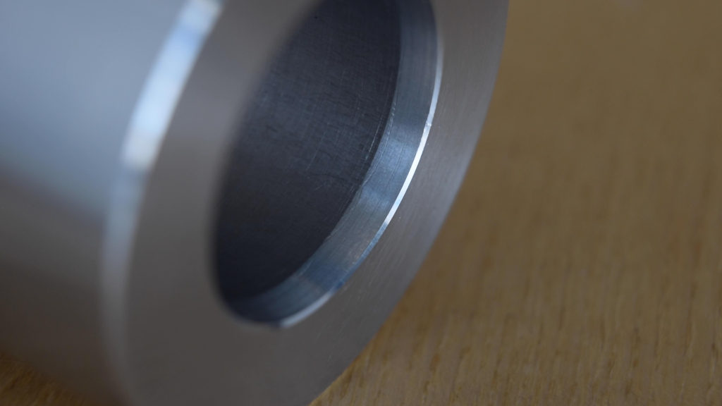
When you assemble the components, you need to squeeze the O-ring quite a bit to create a seal. It helps to have a shallow entry angle of about 15 degrees. This surface should be totally smooth and free of burrs so that the ring isn’t inadvertently cut.
Surface finish on the components is extremely important. As a general rule, the side of the gland, and the bore or rod, should have a 32 rms surface finish for static seals. The walls of the gland can be slightly rougher, at 64. This is where the piston seal really shines, since it’s typically more difficult to verify the dimensions and finish on a rod seal gland.
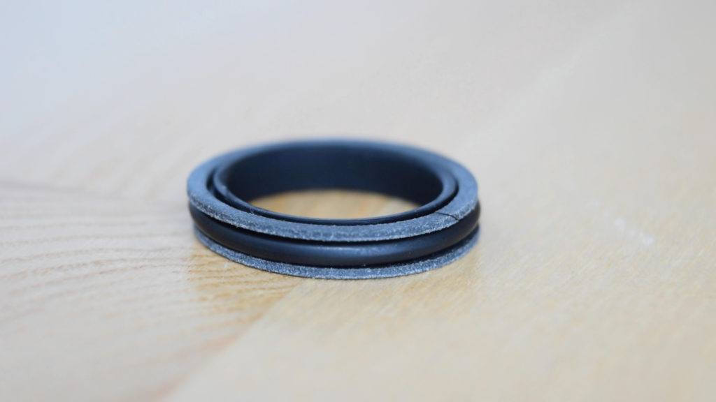
In a dynamic application, O-rings can work, but there are much better options to consider. This is called a T-seal and they are specifically designed for dynamic applications. They are packaged with two backup rings as a unit, and their primary advantage is that they have a wide, flat bottom to keep them from rolling around in the groove. They don’t cost much more than O-rings, and in our experience, are very reliable in dynamic applications.
Up to this point, we haven’t mentioned where the dimensions for the components come from. There are three seal parameters that will define the dimensions: squeeze, stretch, and percent gland fill.
Squeeze is how much you radially compress the O-ring when it’s installed in the gland. In general, 18-25 percent squeeze is appropriate for most static seals, but as high as 30 percent is sometimes used, particularly for cold-service applications.
Stretch corresponds to how much the O-ring is tangentially stretched AFTER it is installed in the groove. It doesn’t directly have to do with how much you stretch the O-ring during installation, though with small sizes of rings, the installation stretch creates other problems. Stretch should be below 5 percent, because high values of stretch cause the cross section to become smaller, decreasing the squeeze.
Volumetric gland fill is the final parameter. The O-ring and backup rings are incompressible, and if you don’t have enough space, you won’t be able to assemble the components because there will be nowhere for the O-ring to go. You also have to watch out for thermal expansion, because the O-ring will get bigger with temperature, and it can actually crush the metal components and yield them if you don’t have enough room. A good guideline is to keep the gland fill below 85%.
While you could use these equations to calculate the gland dimensions yourself, there is a source for pre-calculated values called the Parker O-Ring Handbook.
Unless you have a very unusual or demanding application, the guidelines we’ve given you, and the tables published by Parker should allow you to confidently design reliable O-Ring connections. If you found this video helpful, we’d really appreciate it if you shared it. We have a long list of engineering topics that we’ll be covering in future videos, so be sure to subscribe so you don’t miss these. If you have feedback, a question, or an idea for a future video, be sure to leave a comment!
[…] our recent video about O-rings, we featured some FEA animations of an O-ring being installed in a gland, and then responding to […]
Excellent Oring Instructions/ guidance, I’ve done 20,000 psi and wished I had this reference when I did it decades ago.
Hi friends, I am an engineer and I want to know what program be used for the simulation of the o´ring’s.
Please view our blog post on this topic: https://tarkka.co/2019/04/11/overview-of-hyperelastic-fea-of-o-ring/
As a machinist, I never understood why housings had super tight tolerances on an ID groove.
Especially on applications calling for .0001-.0003 Thick anodize.
By that time, I am stuck holding +/- .0002 to comp for the build up.
I won’t really know the application. But, I can sort of understand why they do that.
Looking forward to learning more.