It’s imperative that design engineers understand the full journey of the parts they design, from the drawing definition, through manufacturing, and inspection. One of the most common features in machine design is a hole. Whether it accepts a bolt or holds a precision bearing, it has to be the right size and in the right location for the machine to function properly. In this video, we’ll outline the considerations for designing holes and precision bores, give you some tips for machining them reliably and cost-effectively, and compare the different ways they may be inspected.
Video Chapters
00:00 – Introduction
00:47 – Precision Bores in Machine Design
02:36 – Limits of Size of Holes
03:03 – GD&T Location Controls
03:55 – GD&T Form Controls
04:43 – GD&T Orientation Controls
05:31 – Surface Finish
06:26 – Drilled Holes
07:33 – Tips for Using Drills
08:23 – Spot Drills
09:44 – Reamers
11:26 – Boring
12:27 – Circular Milling
13:07 – In-Control Compensation (G41/G42)
14:28 – Accuracy of Machining Processes
16:21 – Inspection of Precision Holes
17:03 – Plug Gauges (Go/No-Go Pins)
17:54 – Calipers for ID Measurements
18:26 – Telescoping Bore Gauges
19:00 – Tubular ID Micrometer
19:36 – Dial Bore Gauge
20:19 – Tri-Point Micrometer
21:45 – How to Confirm a Bore is In-Spec
23:10 – Rule 1, The Envelope Principle
24:01 – ISO vs. ASME for Features of Size
25:31 – Conclusion
Additional Resources
- Mitutoyo, Quick Guide to Precision Measuring Instruments
- Provides a great background of how to select and use various types of manual and digital measuring tools and account for their associated errors.
- US Air Force, Aeronautical Design Standard AND10387
- Lists generally accepted size tolerances for drilled holes.
- Edge Precision, Cutter Compensation a Small Explanation
- One of the best explanations available of how to setup G41/G42 in-control compensation for CNC milling.
Video Transcript
Precision bores and holes are fundamental features in nearly every machine. If you’ve ever designed something with a dowel pin, bearing, or seal, you’ve undoubtedly had to specify a precision hole.
In this video, we’ll give you an overview of the primary hole-making techniques used in industry, and show you some best practices for design so that you don’t add unnecessary cost to your parts or create problems during manufacturing. We’ll also give you some tips for getting great results with common tools and equipment when machining. And since the foundation of precision machining is precision measurement, we’ll discuss some metrology considerations so that you can measure your parts quickly and accurately every time.
First, let’s talk about some examples in machine design where you would need to specify a precision bore. This ball bearing is mounted in an aluminum housing. The bore it fits must be very precisely made if the bearing is to function properly. If the fit between the bearing and the housing is too tight, the bearing might lock up once it is installed, or fail prematurely. If the fit is too loose, the bearing may shift around during operation, leading to vibration or other problems in the machine.
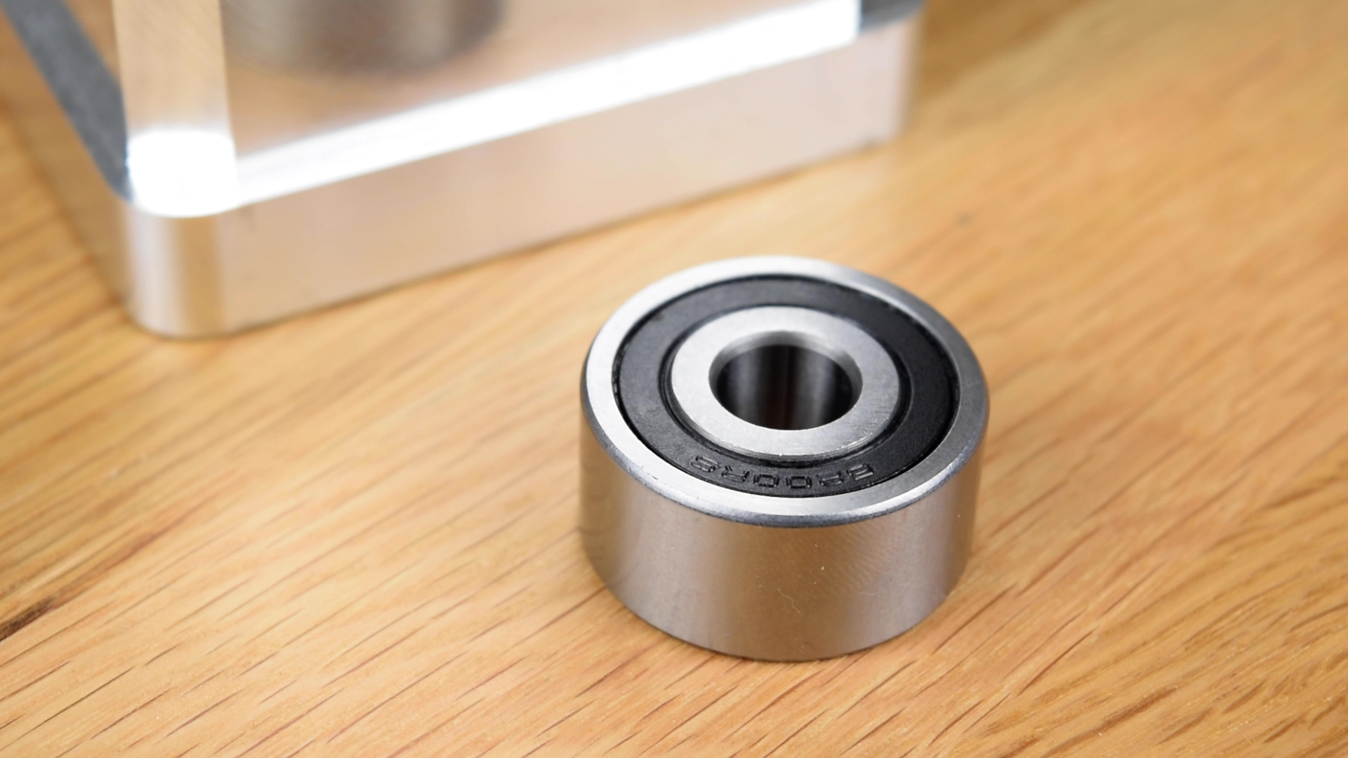
For this bearing, the difference between a bore that is “too-tight” and one that is “too-loose” is only about five ten-thousandths of an inch, or 12 microns. That is a very tight tolerance, and it requires some care to machine and inspect correctly.
Another example of a precision hole is a seal bore. As we discussed in our video on O-rings, seals rely on a carefully-controlled amount of interference with the bore. If the fit is too tight, the piston could bind. Too loose, and the seal may leak or extrude into the gap between the piston and bore.
Finally, designers often align components or transmit force using dowel pins. One common scheme is to design the joint such that the pins press into one part, and the other part freely slips over them. Achieving these fits requires not only the size of the holes be accurate, but also that they are drilled in the correct locations.
With these applications in mind, let’s think a little more carefully about the specific qualities of a bore that impact its performance, and discuss how we might control these qualities on an engineering drawing. The most obvious characteristic that comes to mind is size. If a hole is too small, the mating part won’t fit. And if it’s too big, it may not provide the precision alignment that is required. The designer uses a tolerance to specify the range of sizes that is acceptable for the finished feature. We’ve shown you before how to systematically set this tolerance based on the desired fit between components.
But a hole’s size isn’t the only characteristic we need to worry about. If you’ve ever tried to align two parts with a pattern of screws or dowel pins, you may have encountered first-hand the importance of a hole’s location. In this case, even if the sizes of all the holes involved are within tolerance, you might find that the parts still don’t fit together. This is because the holes must also be in their correct locations for the joint to function as intended. While the location tolerance can be controlled with conventional linear dimensions, geometric dimensioning and tolerancing, or GD&T, allows the designer much more specific control over the position tolerances of features, and also increases the amount of allowable tolerance without impacting functionality.
But size and location tolerances still aren’t enough to fully-define the dimensional characteristics of a hole. A bore, even a very precisely machined one, is never a perfect cylinder. There are always tiny variations, high spots and low spots, that deviate from a perfect cylinder. The amount of allowable variation from a perfectly round, straight cylinder is controlled with a form tolerance. For cylinders, the GD&T tolerances of straightness, circularity, and cylindricity are the primary ways the designer specifies form requirements. If you are working to ASME drafting standards, there is also an implicit form control that we’ll talk more about a bit later.
There is another dimensional property, called orientation, that can also have a big impact on machine performance. Orientation is used to describe how parallel or perpendicular a bore must be to another feature. When bearing bores, for example, have excessive angular misalignment, the shaft can bind-up during installation, or cause undesired forces and moments during operation, leading to premature failure.
There is a lot of nuance in tolerances of location, orientation, and form, and we just want to introduce you to these concepts at a high level for now. In subsequent videos, we’ll focus more on the specifics of these controls, especially as they pertain to GD&T.
The last characteristic of a hole is the quality of its surface finish. Surface finish is especially important when working with hydraulic or pneumatic seals, as a finish that is too rough will increase the chance of leaks, or lead to premature wear of the sealing elements.
Precision holes can be manufactured by a number of different techniques, and the machinist must balance the tradeoffs of each in order to choose the most economical process that meets the drawing requirements. The four primary processes for forming and refining holes are drilling, reaming, boring, and circular interpolation with an end mill. There are lots of other processes, but these four are widely available in nearly every machine shop. Let’s talk about each of these in a bit more detail.
Drilling is probably the most familiar machining process. Drill bits used in metalworking have two angled cutting edges that meet at a center point. Unlike an end mill, the flutes of a twist drill are not cutting surfaces. Their sole function is to work like an auger, conveying the chips up and out of the hole.
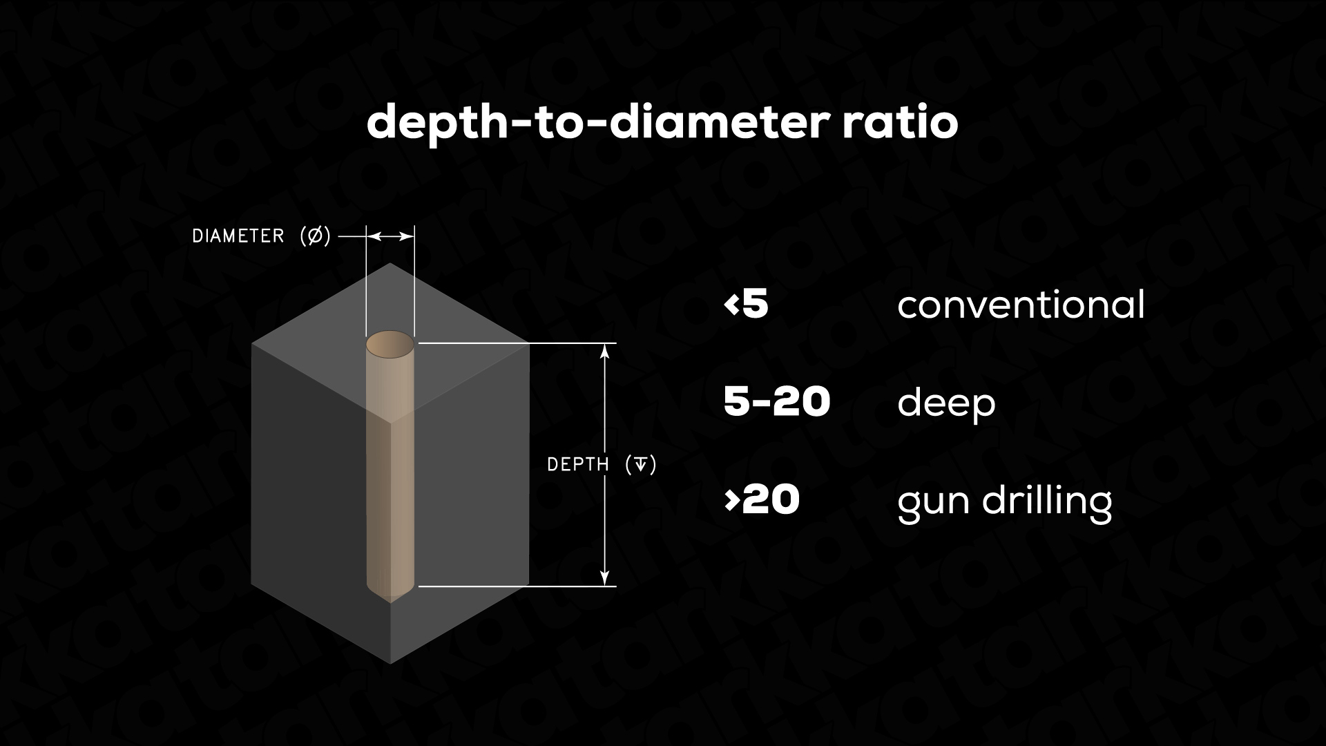
For the designer, an important consideration for a drilled hole is the ratio between its depth and diameter. For example, if a hole’s diameter is one-half inch, and its depth is two inches, we would say that it has a depth-to-diameter ratio of four. Holes with depth-to-diameter ratios of five and above are generally considered “deep” and may require special drilling cycles and tooling that add cost to the part.
The designer also must be aware that holes can only be drilled normal to a surface. If you need a hole on a curved or angled face, you should specify a spot-face, which creates a flat bottom to work from.
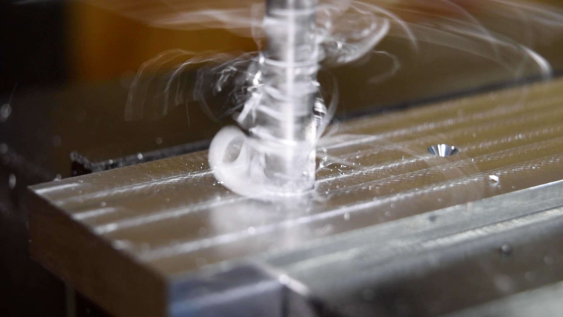
For the machinist, the primary concern when drilling is chip evacuation. On deeper holes, especially in aluminum, chips tend to get stuck in the flutes of the drill, which dramatically increases the heat generation during cutting.
By far, the best way to mitigate this problem is with through-spindle coolant. This system delivers high-pressure coolant right to the cutting edge of the drill. As the coolant flows back out of the hole being drilled, it carries the chips with it. If through-spindle coolant isn’t available, pecking cycles can help, and there are also drills with parabolic flute geometry that are designed to more effectively lift chips from the hole. Lowering the spindle speed while maintaining the same feed-per-rev can also help by reducing the heat generation, making the chips less likely to weld-up.
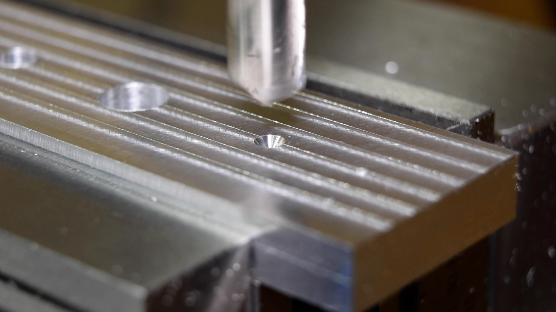
If you want to drill a hole without the bit wandering on the workpiece, it is imperative that you start with a good spot drill. Spot drills are much shorter than normal twist drills, and also have very short flutes. This makes them much more rigid than a typical drill, providing an accurate starting cone to help guide subsequent drilling operations.
Typically, the spot drill angle is chosen to be equal to, or greater than the drill point angle. The idea is that you want the center of the drill to make contact, and begin cutting, before the outside edges. The diameter of the cone left on the workpiece by the spot drill should be about 75% of the diameter of the drill you plan to use.
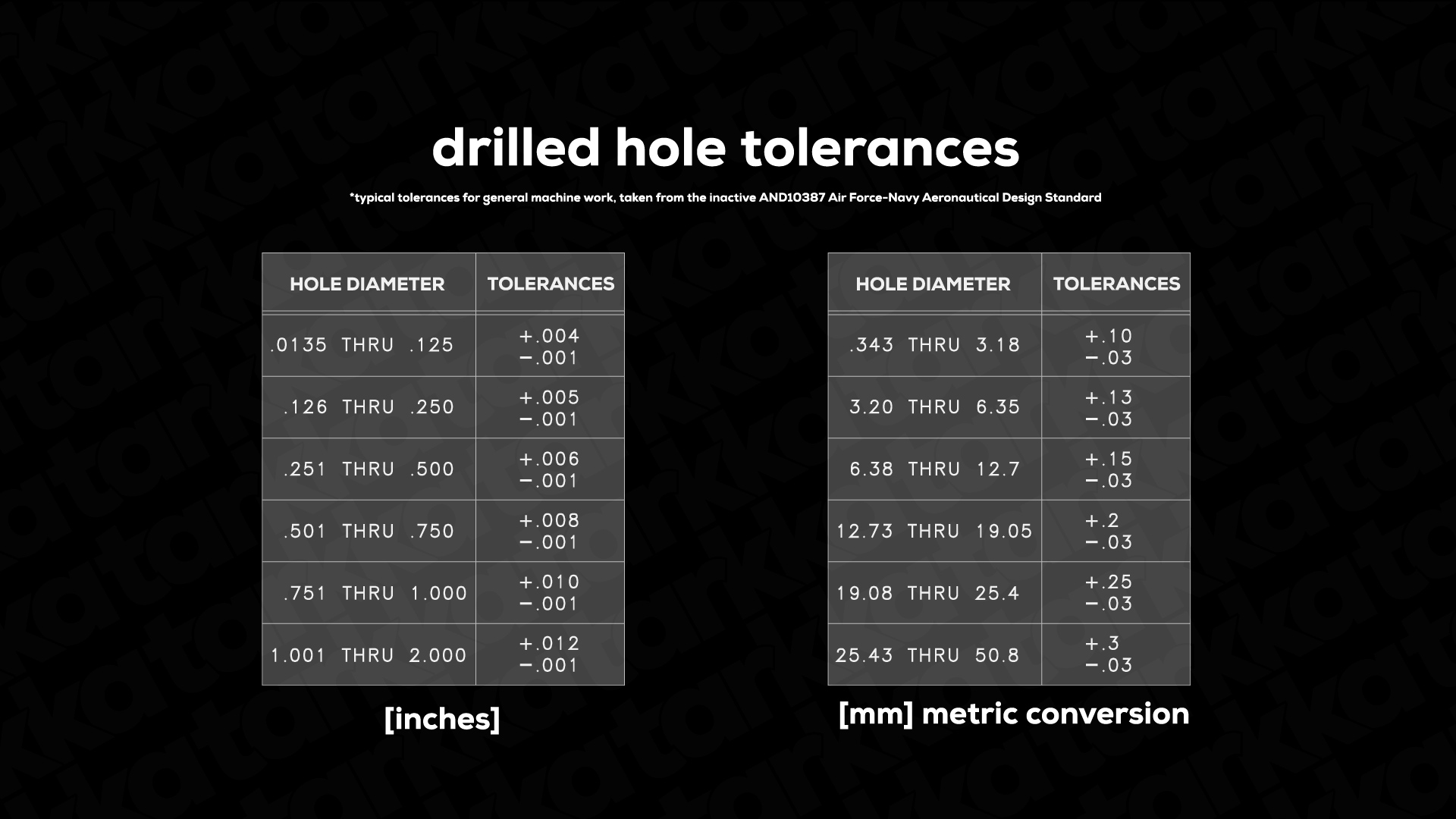
Even with careful spot drilling and an optimized process, drilling is not considered to be a particularly precise technique. This table shows the generally expected size tolerances of a drilled hole for a range of sizes. When drilling on a machine tool, the expected position tolerance should be no tighter than an eight thou, or 0.2 mm, diameter.
While drilling, on its own, isn’t a particularly precise process, drilled holes are often refined by subsequent operations to improve their accuracy. When the size of a hole requires a tighter tolerance than drilling alone affords, the hole can be finished by reaming.
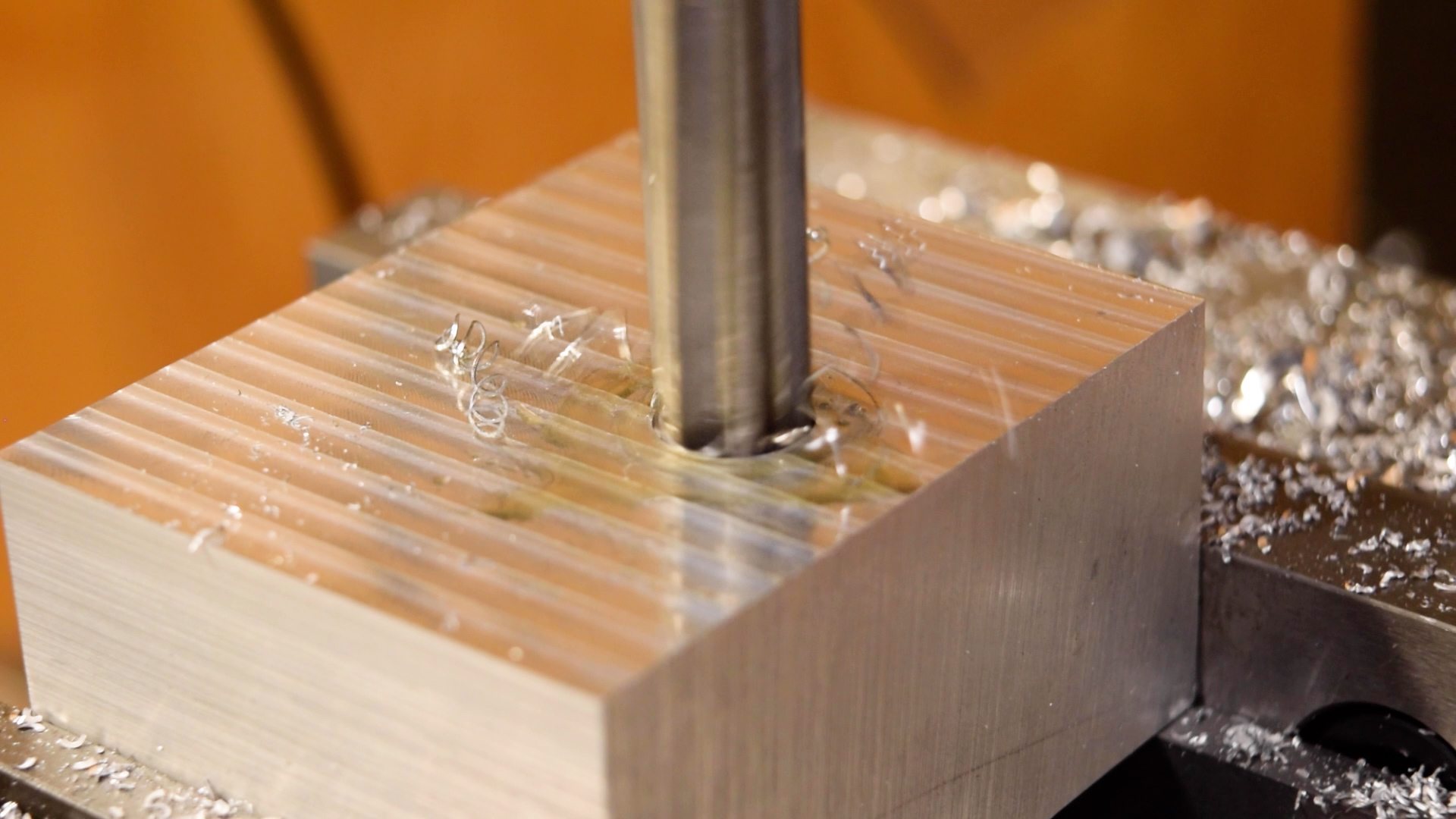
A reamer is a fluted cutting tool that removes a thin layer of material, enlarging the hole by about ten to fifteen thousandths, or .25 to .5 mm. Traditional chucking reamers have a small chamfer on their nose, which does the majority of the cutting. Where drilling can obtain size tolerances on the order of plus or minus five thou, or a hundred microns, reaming can reliably hold tolerances inside of a thousandth, or 25 microns.
As a rough rule of thumb, you should run a reamer at half the speed, and twice the feed-per-rev, of the drill you just used. You should also cut any edge break or chamfer before reaming. This lead-in will help center the reamer, and will also allow it to remove the small burr left by the chamfering operation.
You can sometimes “adjust” the size that the reamer cuts by a few tenths just by changing the cutting fluid or the feed and speed. Generally speaking, a thicker, more lubricous cutting oil, slower speed, and higher feed, will produce a slightly smaller hole for a given material.
A reamer cannot correct issues with location or form on drilled holes. Reamers are actually designed to be very flexible, self-centering on the pilot hole and following its profile. If the drilled hole is in the wrong location, or isn’t straight, reaming it won’t improve the situation very much.
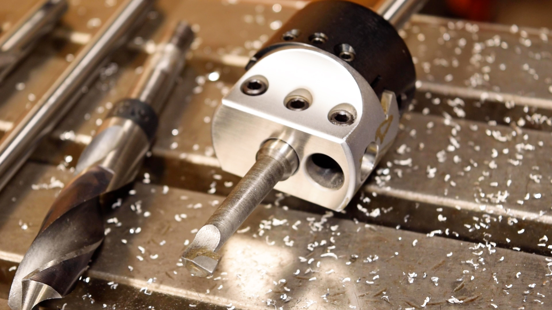
When you need to make very straight, round holes at very accurate locations, boring is the gold standard. Boring heads feature an eccentric cutter, often a lathe boring bar, which is slowly fed into the bore. Unlike a reamer, which can only cut one size of hole, a boring head is adjustable, allowing a wide range of diameters to be machined with a single tool.
Setting up boring heads is a fairly slow process, but once they are dialed in, they can reliably hold size and location tolerances of a few tenths, or around 5 microns, depending on spindle runout and machine table accuracy.
Before CNC machines became widely available, boring was much more common than it is now, especially as a rough-machining operation. With the widespread adoption of CNC machining centers, boring has become more of a high-precision finishing process. Part of the reason boring heads have fallen out of favor is because CNC machines can move multiple axes at once, making it possible to mill circles and complex profiles.
While CNC milling is highly versatile, it is usually not as accurate as some of the processes we’ve covered, especially when it comes to holding a size tolerance. A lot of the reason comes down to CAM programs assuming a perfect nominal diameter for an end mill. In reality, most end mills end up one or two thou, or between 25 and 50 microns, smaller than their nominal size after final grinding.
If you have a probing system available on your machine, you can dramatically increase the accuracy of your milled features by enabling “in-control compensation” for the finish pass. When a part program invokes in-control compensation, usually with a G41 or G42 block, the machine tool controller calculates the offset of the tool’s center line using the measured diameter of the specific tool loaded in the spindle, as opposed to the generic nominal tool diameter stored in the CAM software’s tool library. This compensation, when available, can increase the accuracy of milling to within one or two thou, or between 25 and 50 microns.
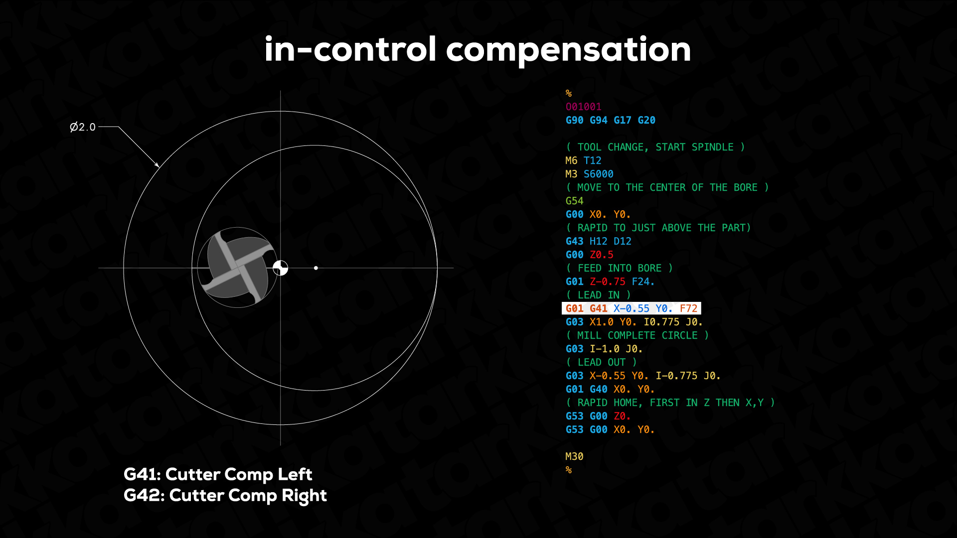
However, in-control compensation can’t account for tool deflection, which often causes a bore’s diameter to vary in size along its length. And without regular backlash calibration, CNC mills that are heavily used tend to cut distorted circles as the ball screws wear over time. While the versatility of CNC milling makes it an appealing option, it’s important to emphasize that drilling, reaming, and boring, still have their places, especially when tight tolerances are required.
If we want to compare the process capabilities of the four techniques we’ve covered, it’s best to think about size and location accuracy independently. If even greater precision is required, honing, grinding, jig boring, or roller burnishing may be considered. However, these are specialized processes that can add substantial cost to a finished part. Often, the best approach involves combining multiple processes, leveraging the strengths of each.

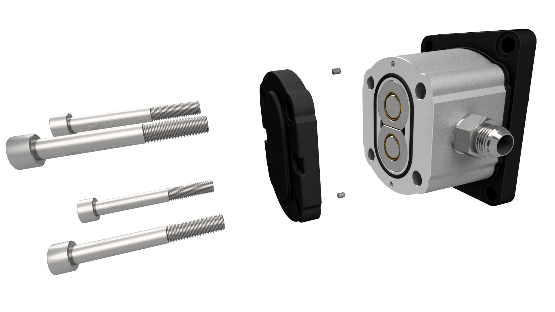
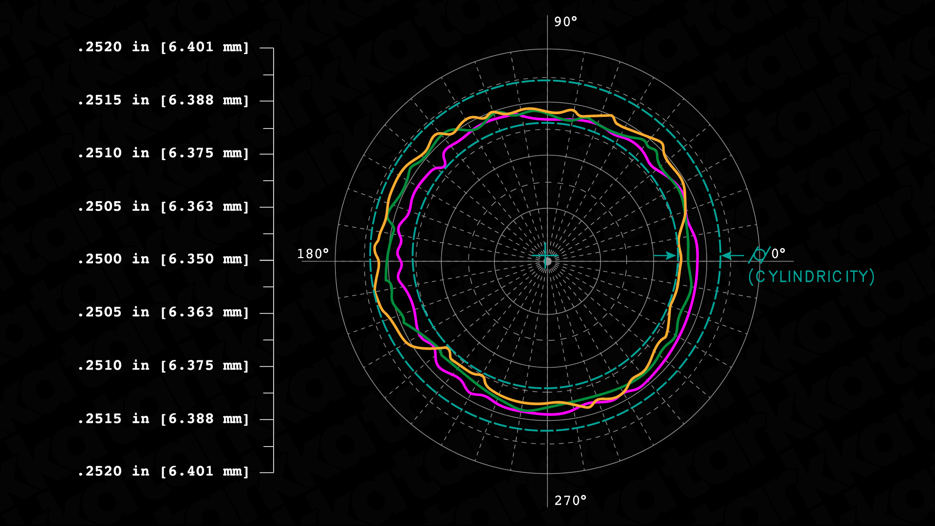
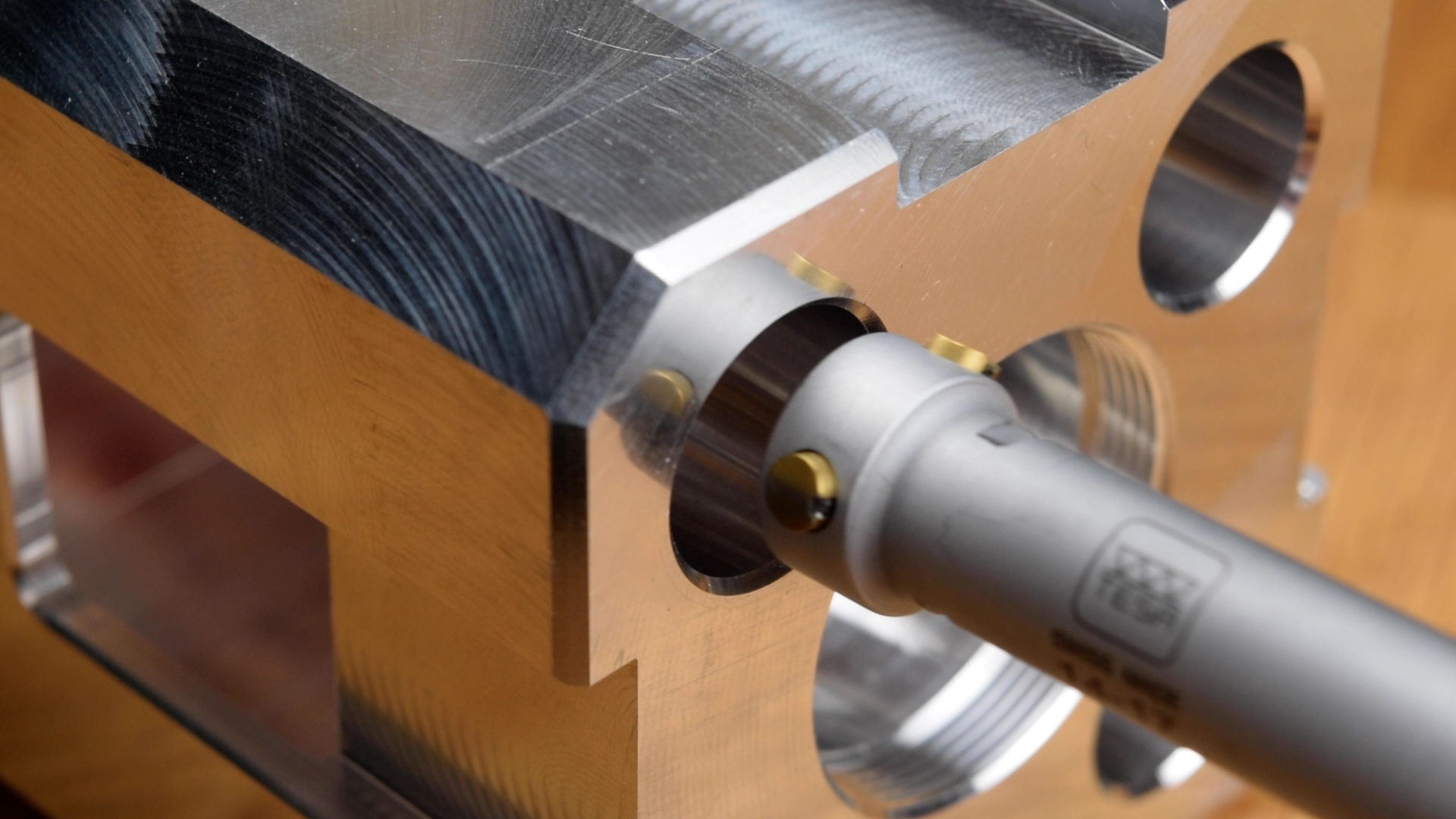
This is a functional gauge we machined for an upcoming video about the GD&T position tolerance. Gauges like this can be used to quickly confirm that patterns of features meet GD&T position tolerance requirements. If the part is able to fully seat on the gauge, then it is in-spec.
This gauge features a steel base with four pins pressed into it. The press fit between the pins and the base requires the receiving holes in the base to be very carefully sized. And since the point of this part is to be a precision position gauge, the pins also need to be in very accurate locations. At a quarter-inch in diameter, these holes were too small for boring, at least with the tools we had on hand.
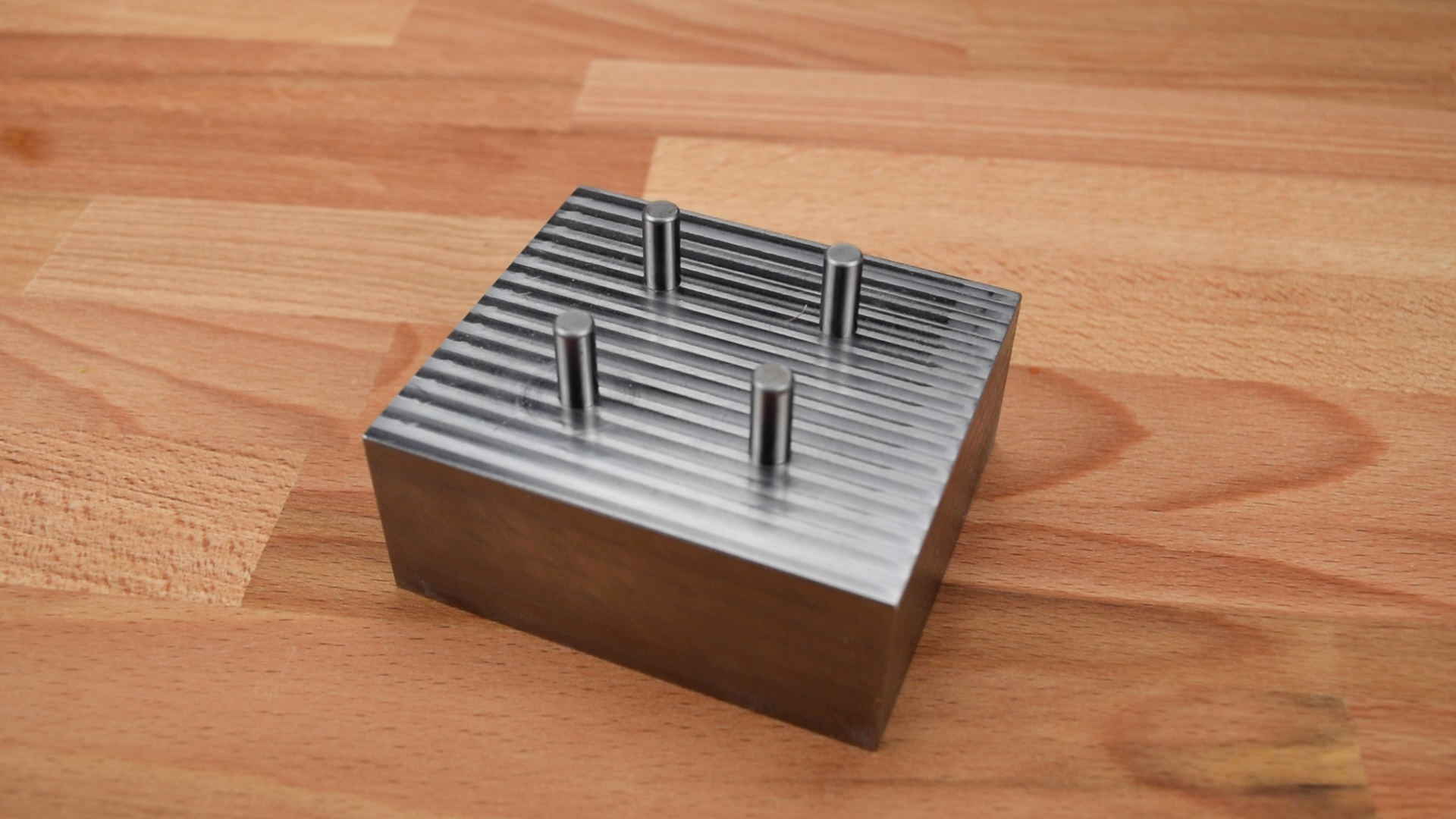
What we chose to do is first drill the holes undersized to remove the majority of the material. At this point, the holes were neither accurately sized, nor accurately located. Then, we followed with an end mill, and skimmed a bit more material off the sides of the holes. This refined their locations, allowing us to ream them to final size for a perfect press fit.
When we inspected the gauge, the location and orientation deviations of the pins were less than two-tenths, or five microns, which is within our tolerance for this gauge.
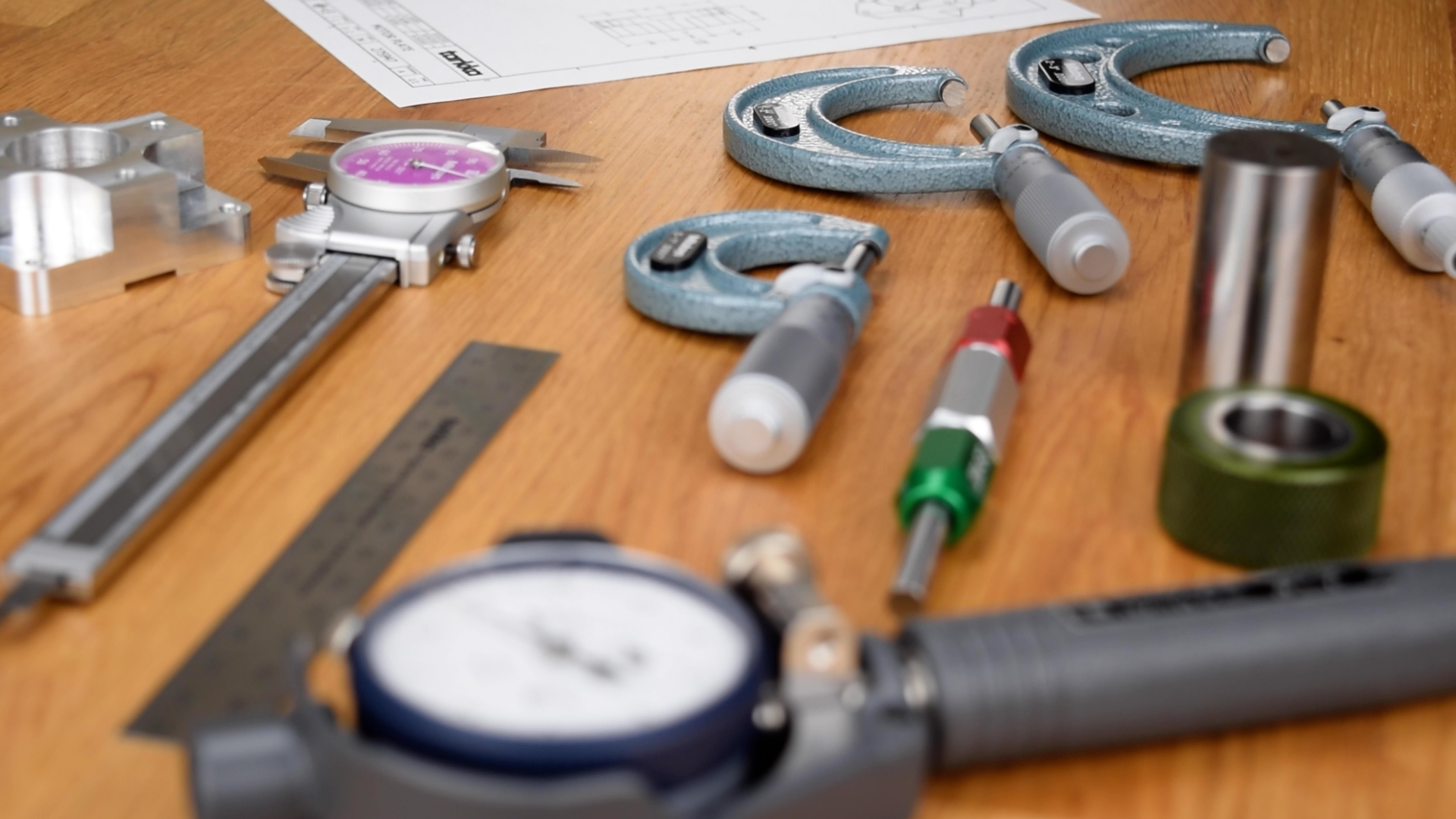
In precision work, inspection and metrology are critically important. If you can’t inspect to a tight tolerance, you can’t machine to a tight tolerance. It’s as simple as that.
When it comes to measuring holes and bores, there are a number of different tools and techniques available, but the right choice in a given situation depends on a couple of factors. For one, you should ask yourself, do I actually need to measure the diameter of the hole, or do I just need to confirm that it is in-spec? The answer to this question may depend on a customer’s quality control plan, but often times we don’t actually need to measure a hole directly.
Instead, we can use “go” and “no-go” plug gauges for the lower and upper tolerance limits, respectively, to confirm that a part is in-spec. This approach is the most efficient, by far, and for that reason, it is a common quality-control technique in high-volume production work.
However, plug gauges become problematic when tolerances are very tight, like less than two thou or 50 microns. At these tolerances, it can be difficult to repeatably discern the difference between a “go” and a “no-go.” Pin gauges also can’t assess whether a hole is actually round, and burrs on the edge of the hole can cause a false result. Finally, you will often need an actual numerical measurement of a feature, instead of just an “in-spec” or “out-of-spec” judgment.
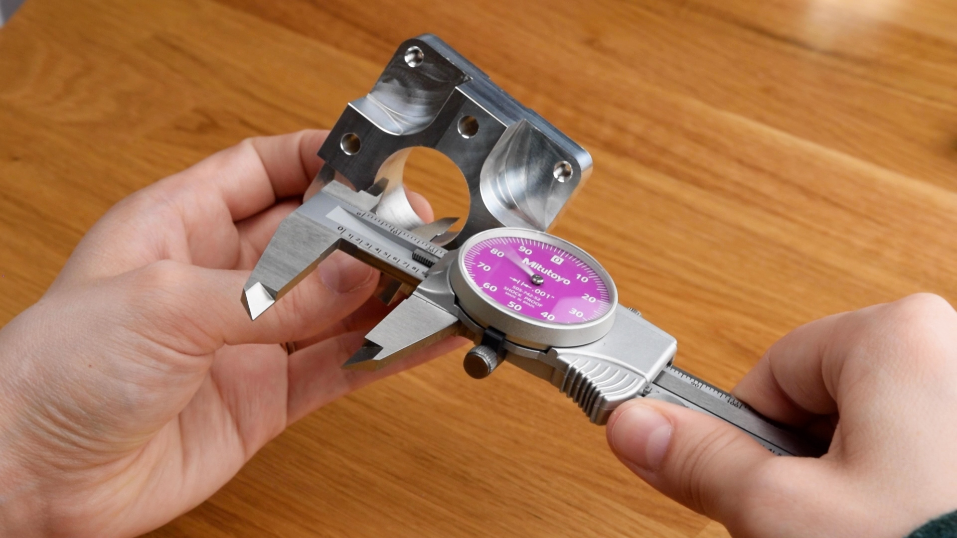
In these situations, you might be tempted to reach for your calipers, and use their inside measurement jaws to check a diameter.
Don’t.
The outside jaws of ordinary calipers are only accurate to plus or minus one thou, or 20 microns, and because of something called scale shift error, the inside jaws are allowed an additional plus or minus one thou, or thirty microns of deviation, meaning that your measurement could be off by up to two thousandths of an inch, or fifty microns. There are some better options to consider.
Slightly better than calipers are telescoping bore gauges. These tools help “transfer” an inside measurement to an outside-measuring tool like micrometers. Telescoping gauges are tricky to use, but if you’re careful, you can get a measurement that repeats within one thou or 25 microns. The biggest advantage of telescoping bore gauges is that they are cheap. The tradeoff is that they are highly sensitive to operator technique, and even under ideal circumstances, aren’t accurate enough for very tight tolerances.
For more accurate measurements, you might consider tubular ID micrometers. These are usually sold in kits that include a micrometer head and several interchangeable anvils. A big advantage of tubular ID mics is that a single kit can cover a wide range of diameters. This set, for example, can measure from 1.5 inches to 12 inches, or 40 mm to 300 mm, but other sets are available that measure up to 60 inches, or 1500 mm. Tubular ID mics are accurate to about one thou, or 25 microns.
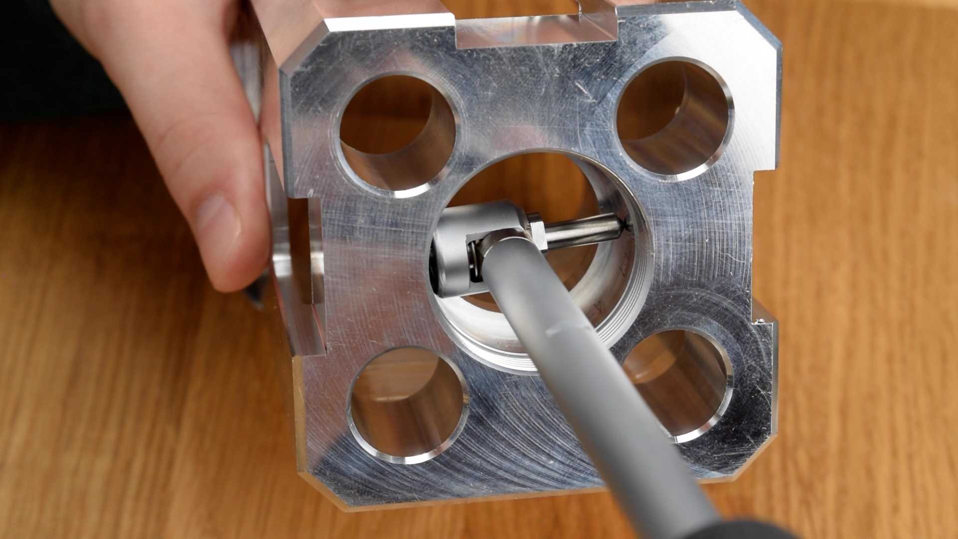
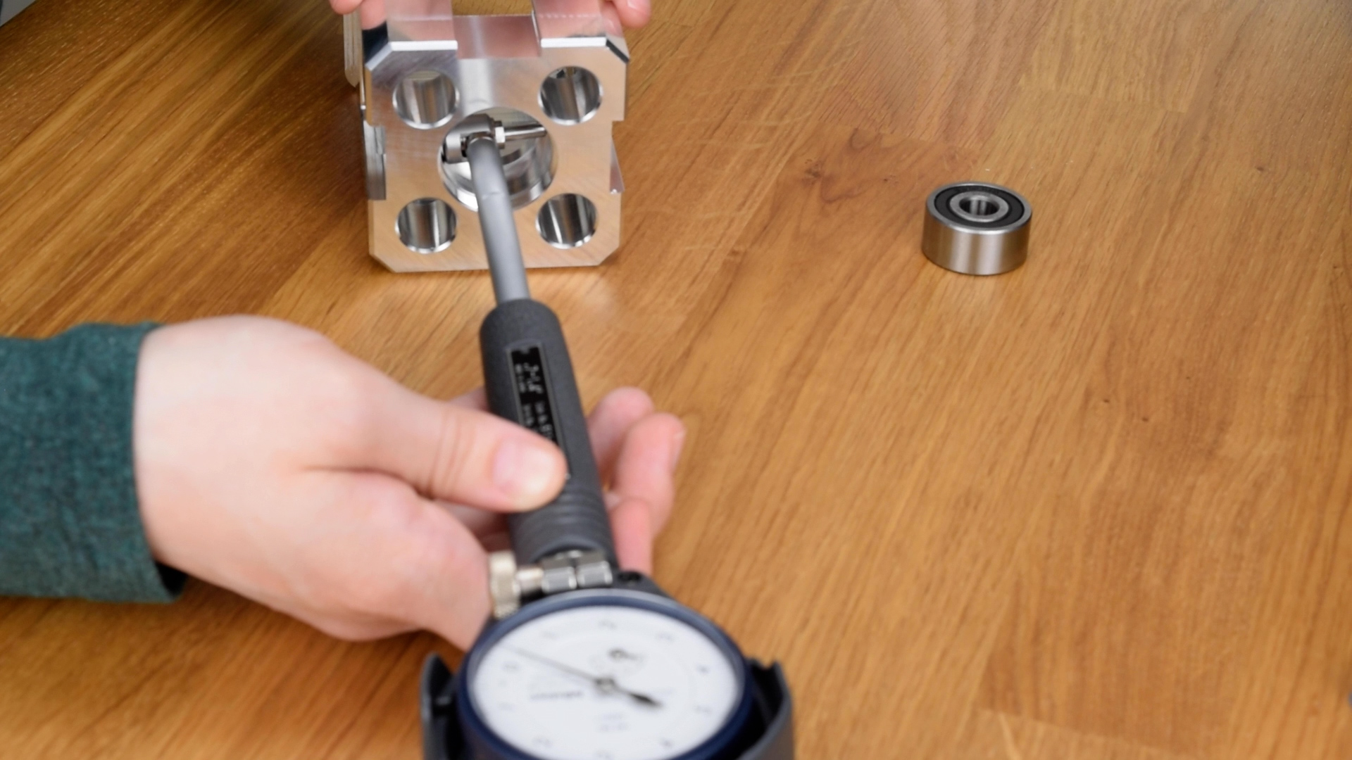
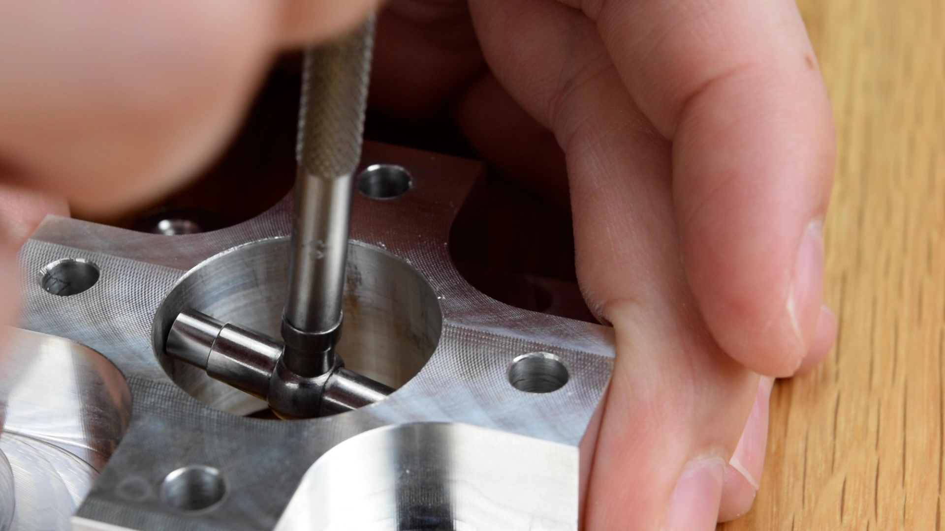
For even more accurate measurements, you may need to use a dial bore gauge. They can read out to a single tenth, or two-and-a-half microns. Dial bore gauges can also be used to quickly take several measurements at different angles and depths in a bore, allowing the operator to assess form.
If you look closely at the scale of a dial bore gauge, you’ll see that it actually does not read out the diameter of the feature you’re measuring directly. Instead, it only reports a variation from zero. Hence, the gauge must be set before use. The preferred approach is to use a ring gauge for the diameter being measured, but you can also set them between the jaws of a micrometer.
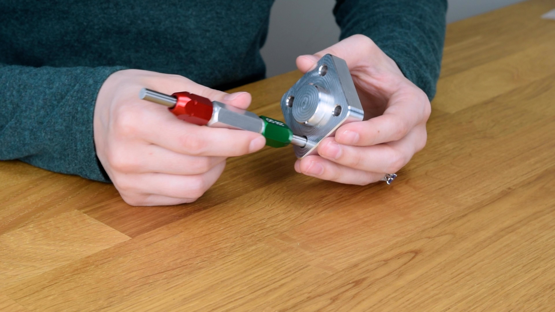
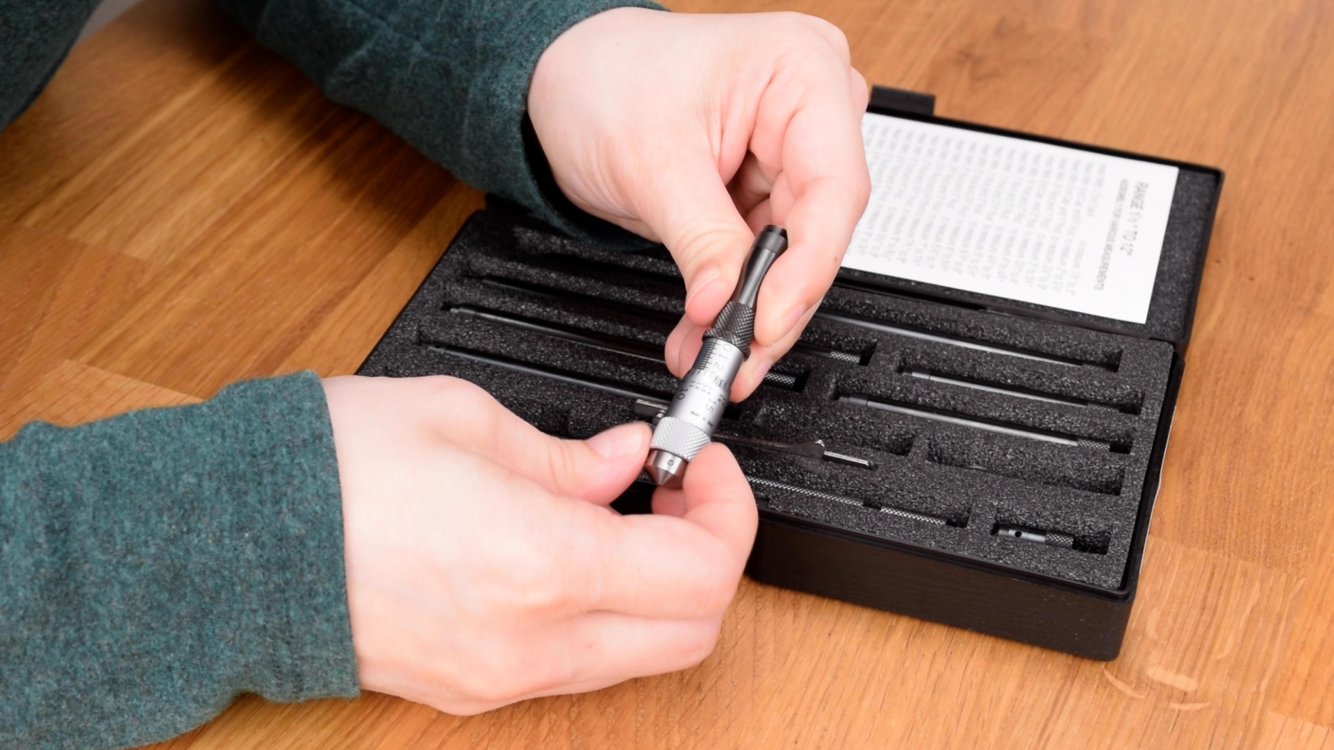
A variation of the dial bore gauge is the tri-point micrometer. Tri-point mics offer two big improvements over dial bore gauges. First, there are three measuring surfaces, instead of two, which self-center the gauge in the bore, eliminating the need for the rocking motion. This makes them faster and easier to use. Second, tri-point mics are usually direct-indicating, meaning that they display an actual diameter, instead of just a variance like a dial bore gauge does. This means they don’t need to be set with a ring gauge, unless you’re changing the measuring head.
These advantages come at a cost: Tri-point mics are substantially more expensive than dial bore gauges, and they are among the most-expensive of all manual measuring tools. The measurement range of each head is also fairly limited, so you need to have a pretty large inventory of these on hand to be able to inspect every bore using them.
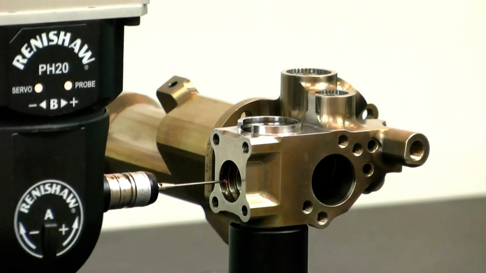
It’s also worth mentioning that you can also measure bores using a coordinate measuring machine, or CMM. While CMM’s are usually very accurate, they can also be easily misused. Very minor issues with setup, programming, or reporting can generate significant errors in the final data. Even when a CMM is available, there is a good chance that a manual tool will provide a more accurate measurement more quickly.
We’ve given you a few ways that a feature can be measured, but determining if it is actually in-spec per the drawing requirements isn’t as easy as just writing down the number displayed on the gauge. We mentioned earlier in the video that a hole may have subtle variations in form, which is another way of saying that it might not be round or straight, and we have to consider this possibility when inspecting parts.
Suppose you measure a bore in a few different places, perhaps at different depths and angles. You will probably get a slightly different diameter for each measurement. So, what’s the true diameter of the hole? And, what if one or two of the measurements taken are actually outside of the tolerance limits? Is the part scrap?
This is where things get tricky.
From an inspection standpoint, assessing conformance of a cylindrical bore under the ASME Y14.5 system actually requires two steps. First, a two-point measuring instrument must be used to measure the diameter at a variety of different depths and angles. Every measurement taken must lie within the stated tolerances. If any measurement you take is outside of the tolerance limits, the feature is not in-spec. Next, a “go” pin gauge for the minimum diameter limit must completely pass.
In GD&T classes and books, this second step is sometimes referred to as “Rule 1” or the envelope principle. While this two-step approach adds a lot of complexity, there is a good reason for it. Without the envelope principle, bores that measure in-spec aren’t guaranteed to freely assemble with the mating part. If a bore is near its minimum diameter limit, and also has a straightness issue, you can see how the mating pin will tend to bind-up in what should be a running fit.
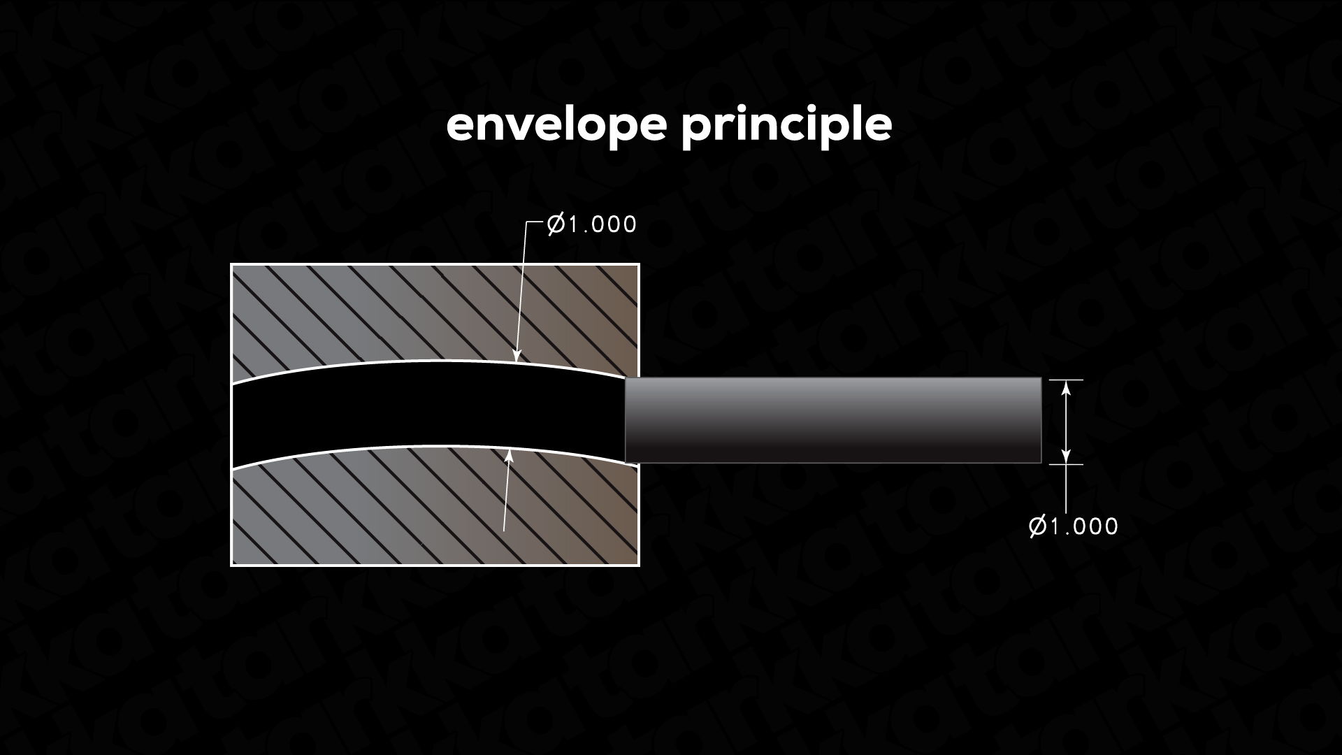
Up to this point, we’ve discussed this concept purely in the context of bores, but the same principle applies to outside diameters too. Every two-point measurement taken with OD micrometers must be within tolerance, and a ring gauge at the maximum diameter limit must also pass over the feature.
If you’ve worked with GD&T before, you’ve probably heard someone cryptically state that there are differences between the ASME and ISO GD&T systems. Well, the biggest difference has to do with the envelope principle. It applies by default on drawings prepared to ASME Y14.5, but not on ISO. ISO drawings, by default, rely only on the two-point measurement scheme. In other words, the only requirement under the ISO system is that every two-point measurement taken, at a variety of angles and depths, lie within the stated tolerance range.
This means that there is no straightness control assumed by the size tolerance. In other words, under the ISO system, it is possible that a feature can be in-spec based on its size tolerance, but still not fit with its mating part.

We won’t get into a debate of which system is better. There are advantages and disadvantages to each, but what’s important is that you understand the differences. If you need the envelope principle when using the ISO system, you can add the envelope modifier after the tolerance, which makes the interpretation equivalent to the ASME system.
Likewise, if you have an ASME drawing, and you need forgo the requirements of the envelope principle, you can add the independency modifier, which calls for the diameter to be treated as it would be under the ISO system.
Hopefully this video has given you some tips for designing and making precision parts. As always, we have a companion blog post with additional resources and references if you want more information. And if you find our content helpful, consider subscribing to our channel as well as our newsletter so you don’t miss any future videos.
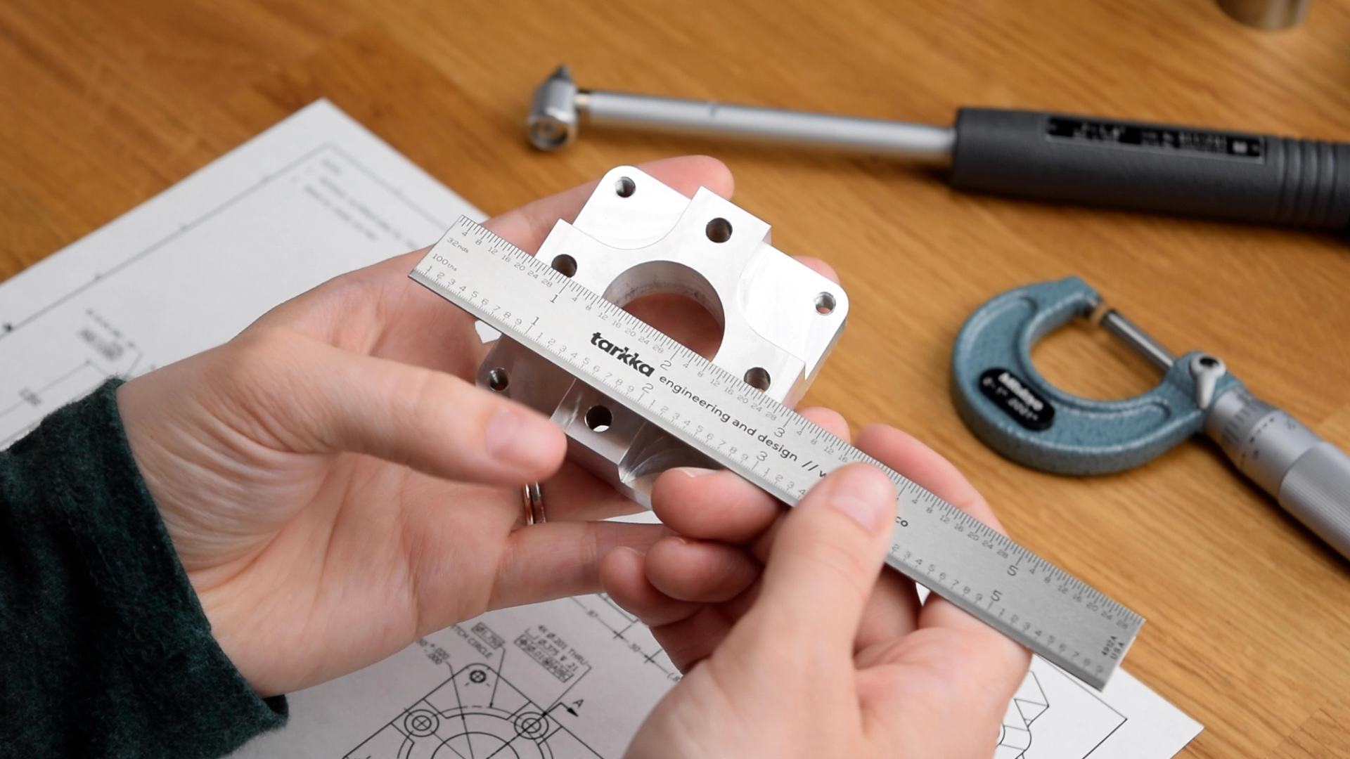
And if you want to support the channel, we have an online shop where you’ll find a bunch of helpful engineering tools, like this ruler. A steel ruler is a fundamental tool for any engineer or machinist. We had these made to our exact specifications by a small business here in the USA. And unlike some of our earlier videos, this ruler has both imperial and metric units.
If you have any questions or feedback, be sure to leave a comment. You can also find us on LinkedIn or our other social accounts, which we’ve linked to in the description. Thanks for watching!